HT16K33 16x8 Dot-Matrix Display
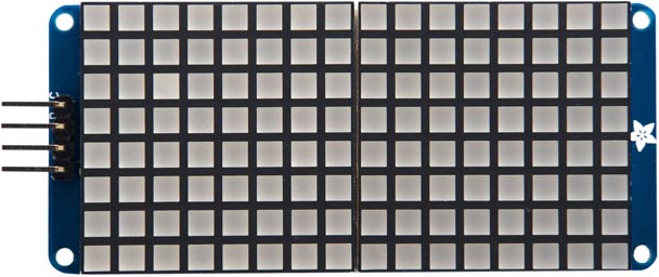
These routines are for a 16x8 LED matrix based on an HT16K33 [1] I2C driver. It's available from Adafruit [2] in a variety of colours, and with square or round LEDs:

The 16x8 backpack is like two HT16K33 8x8 Dot-Matrix Display backpacks, but using a single driver for the two displays. These routines provide the following options:
- Display a 16x8 bitmap.
- Plot a point on a 16x8 grid.
- Display four digits, each from 0 to 9, using a 3x7 matrix for each character, with the ability to customise the appearance of each digit.
You can select from eight I2C addresses using solder links on the back of the board; the default I2C address with no links is #x70 or 112.
Initialising the display
The variable adr is used to specify the I2C address of the display:
(defvar adr 112)
The routine set initialises the display and sets the brightness, from 0 (off) to 15 (maximum):
(defun set (bri)
  (with-i2c (s adr)
    (write-byte #x21 s)
    (restart-i2c s)
    (write-byte #x81 s)
    (restart-i2c s)
    (write-byte (+ #xe0 bri) s)))
The routine clr clears the display by setting each row to zero:
(defun clr ()
  (with-i2c (s adr)
    (dotimes (x 17)
      (write-byte #x00 s))))
Displaying a bitmap
The following routine bit displays a 16x8 bitmap on the display:
(defun bit (dat)
  (with-i2c (s adr)
    (write-byte 0 s)
    (dotimes (n 8)
      (let ((col (nth n dat)))
        (write-byte col s)
        (write-byte (ash col -8) s)
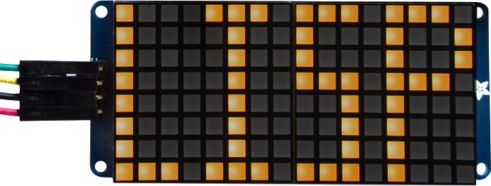
For example, to define a bitmap for "LISP":
(defvar lsp '(#b0111011101110001
              #b1001000100100001
              #b1001000100100001
              #b0111011100100001
              #b0001010000100001
              #b0001010000100001
              #b0001010000100001
              #b0001011101110111))
and then to display it execute:
(bit lsp)

Each element of the list defines one row of the bitmap, reflected left to right; using binary makes it easy to design what you want to display.
Plotting a point
The plt routine treats the display as an 16x8 graphics display, and allows you to toggle one LED on or off by specifying its coordinates:
(defun plt (x y)
  (let ((yy (+ (* (- 7 y) 2) (ash x -3)))
        b)
    (with-i2c (s adr)
      (write-byte yy s)
      (restart-i2c s 1)
      (setq b (read-byte s))
      (restart-i2c s)
      (write-byte yy s)
      (setq b (logxor b (ash 1 (logand x 7))))
      (write-byte b s))))
For example, to toggle the LED in the bottom left-hand corner (with the connector on the left), give the command:
(plt 0 0)
The following command draws two Xs:
(dotimes (x 16) (plt x (logand x 7)) (plt (- 15 x) (logand x 7)))
Displaying digits
The following routine put allows you to display four digits, each from 0 to 9, on the display.
First the list dig is used to store the 3x7 character definitions for each digit:
(defvar dig
  '(#b001010010010010
    #b001101101011101
    #b101100100010101
    #b111010010010101
    #b100100001010101
    #b100101001010101
    #b100010111111010
    0

    #b010010111010111
    #b101101100101001
    #b101101100001001
    #b110010010011011
    #b100101001101100
    #b101101001101101
    #b010010001010010
    0))
The first block defines the digits 0 to 4 and the second block defines the digits 5 to 9.
The routine put then displays four digits on the display:
(defun put (&rest d4)
  (with-i2c (s adr)
    (write-byte 0 s)
    (dotimes (row 8)
      (let ((bit 0))
        (dotimes (d 4)
          (let* ((ch (nth d d4))
                 (k (truncate ch 5)))
            (setq bit
                  (logior
                   bit
                   (ash
                    (logand
                     (ash
                      (nth (+ row (* k 8)) dig)
                      (* (- (* 5 k) ch) 3))
                     #b111)
                    (* d 4))))))
        (write-byte bit s)
        (write-byte (ash bit -8) s)))))
For example, to display the time 12:34 call:
(set 1)
(clr)
(put 1 2 3 4)
- ^ HT16K33 Datasheet on Adafruit.
- ^ 16x8 1.2" LED Matrix + Backpack on Adafruit.
