Ray tracing with uLisp
21st February 2020
This is a simple ray tracer written in uLisp, using the uLisp graphics extensions to plot on a colour TFT display. The scene contains five spheres and a plane and can be run on any of the following boards that include an integral TFT display:
- Adafruit PyGamer and PyBadge (160 x 128)
- ESP32 boards with a TFT display (240 x 135)
- Adafruit Clue (240 x 240)
- Seeed Studio Wio Terminal (320 x 240)
- Sipeed MAiX RISC-V boards (320 x 240)
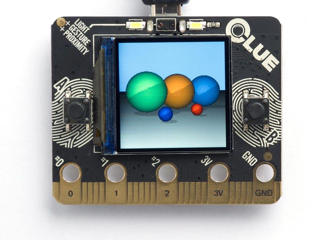
Here's the program running on the Adafruit CLUE:
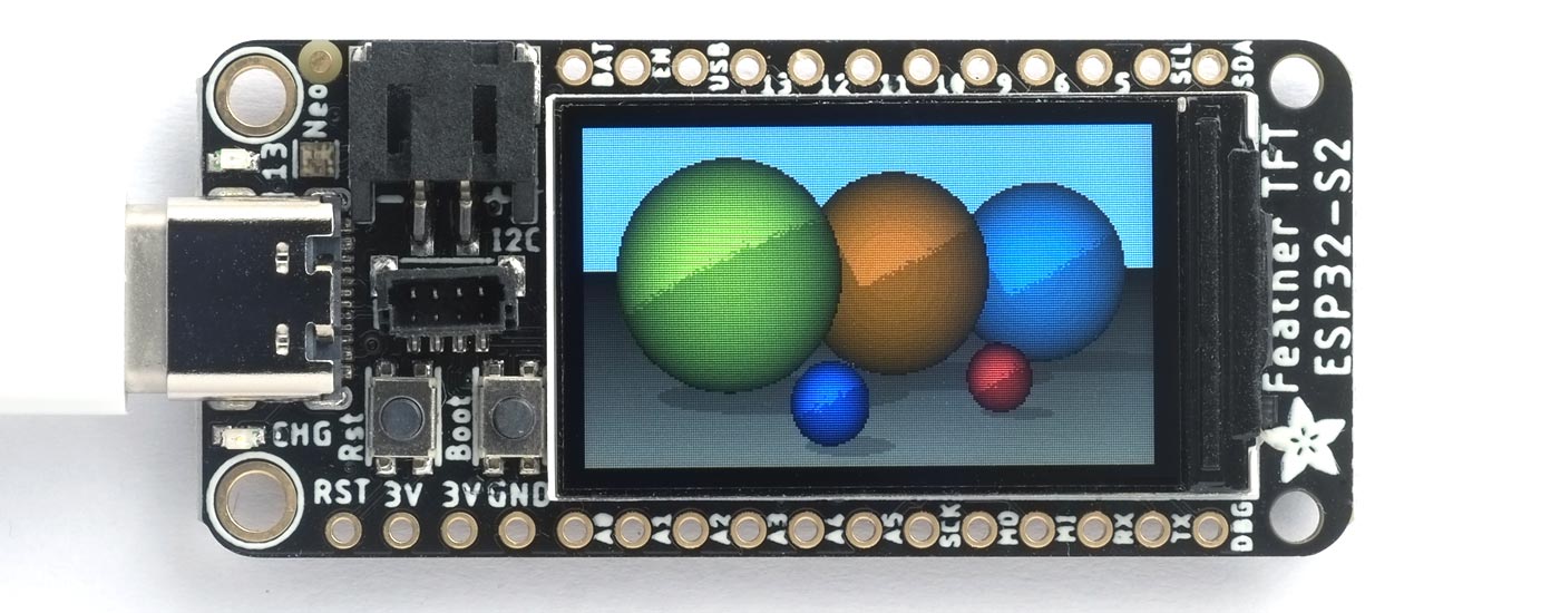
and here is the board running on the Adafruit ESP32-S2 TFT Feather:
Update
24th March 2023: The program and description have been updated to use the uLisp Graphics Extensions.
Running the program
Here are step by step instructions for running the program:
- Download the appropriate version of uLisp for your board from Download uLisp.
- Include the graphics extensions before installing it by enabling the option:
#define gfxsupport
- Use the Arduino IDE to upload it to your board.
- Open the Serial Monitor in the Arduino IDE to display the uLisp prompt.
- Display the ray-tracing program here: Ray tracing program.
- Select the text of the program, copy it, paste it into the Arduino IDE Serial Monitor input field, and press Return.
- Type the following command into the Arduino IDE Serial Monitor input field, followed by Return, to generate the ray-traced image:
(ray-trace width height)
where width and height specify the dimensions of the display you are using.
How ray tracing works
Ray tracing creates a two-dimensional image of a simulated world consisting of one or more three-dimensional objects. It works by considering an image plane, represented by a vertical rectangle in the following diagram:
For each pixel in the image plane, defined by its x and y coordinates, we trace the path of a ray from an imaginary eye, through the pixel, to the objects in the world, here represented by two spheres. The first object hit by the ray determines the colour of the pixel.
In these routines the ray is defined by a starting point pt, usually the eye position, and a unit vector pr specifying the direction of the ray. When the ray hits an object, the hit point is defined by a distance d, which is the distance along the ray from the initial point pt to the hit point. The coordinates of the hit point h can easily be calculated from d, pt, and pr:
h = pt + d x pr
When the ray hits an object in the scene the colour of the object determines the colour of the pixel. A direct hit, normal to the object's surface, produces a bright colour. A glancing hit produces a darker colour, based on its angle to the surface. If the ray doesn't hit any objects the pixel's colour will be determined by the background.
The objects in the scene are rendered as if they are illuminated by a light at the eye position. This world also includes a second light not shown in the above diagram; it's a point light source vertically above the scene, so that the objects will cast shadows.
Utilities
To keep the program as concise as possible points, vectors, and colours are each represented by a list of three elements. The following routines can be used to construct an appropriate vector from its components:
(defun colour (r g b) (list r g b))
(defun point (x y z) (list x y z))
(defun vector (x y z) (list x y z))
Having three separate routines makes the programs more readable by making it clear what type of value we're creating.
Representing vectors in this way allows us to implement vector addition, add, and subtraction, sub, using mapping functions:
(defun add (v w) (mapcar #'+ v w))
(defun sub (v w) (mapcar #'- v w))
Likewise, the dot or scalar product of two vectors, dot, is defined as:
(defun dot (v w) (apply #'+ (mapcar #'* v w)))
and the magnitude of a vector is given by mag, where:
(defun sq (x) (* x x))
(defun mag (v) (sqrt (apply #'+ (mapcar #'sq v))))
The unit vector is:
(defun unit-vector (v)
  (let ((d (mag v)))
    (mapcar (lambda (j) (/ j d)) v)))
and the distance between two points is:
(defun distance (p1 p2)
  (mag (mapcar #'- p1 p2)))
Using mapping functions avoids the need to extract the x, y, and z components of each point or vector, or the r, g, and b components of colours.
Defining the world
The easiest objects to ray trace are spheres, because it's relatively easy to calculate where the ray intersects with a sphere. I've also included an infinite plane object, that gives the other objects in the world something to stand on.
The world, eye, and light are stored in global variables:
(defvar *world* nil)
(defvar *eye* nil)
(defvar *light* nil)
*world* stores a list of the objects in the world. *eye* and *light* give the coordinates of the eye position and point light source.
Objects
I've implemented a very simple object system to deal with the two types of object in the world, spheres and planes. This will make it easy to extend the ray tracer to cope with other objects.
Each object consists of a list starting with the object name, and followed by the object's parameters.
Sphere
A sphere consists of:
('sphere centre radius colour)
where centre and colour are each lists of three items. For example, this is a red sphere at (200, -150, -800) with a radius of 50:
('sphere (point 200 -150 -800) 50 (colour 1 0 0))
The following functions provide convenient ways of accessing the sphere parameters:
(defun sphere-center (s) (second s))
(defun sphere-radius (s) (third s))
(defun sphere-colour (s) (fourth s))
Plane
A plane consists of:
('plane point normal colour)
where point is any point on the plane, and normal is a unit vector giving the direction normal to the plane. Each parameter is a list of three items. For example, this is a white plane:
('plane (point 0 -200 0) (vect 0 -1 0) (colour 2 2 2))
Here are the functions to access the plane parameters:
(defun plane-point (s) (second s))
(defun plane-normal (s) (third s))
(defun plane-colour (s) (fourth s))
Adding an object to the world
The function make adds an object definition to the world:
(defun make (&rest list)
  (push list *world*))
Here are the function calls to define the world:
  (setq *world* nil)
  (setq *eye* (point 0.0 0.0 200.0))
  (setq *light* (point (-5000 10000 -1200)))
  (make 'plane (point 0 -200 0) (vect 0 -1 0) (colour 2 2 2))
  (make 'sphere (point -250 0 -1000) 200 (colour 0 1 .5))
  (make 'sphere (point 50 0 -1200) 200 (colour 1 .5 0))
  (make 'sphere (point 400 0 -1400) 200 (colour 0 .5 1))
  (make 'sphere (point -50 -150 -600) 50 (colour 0 0 1))
  (make 'sphere (point 200 -150 -800) 50 (colour 1 0 0))
The eye is on the z axis, 200 units from the origin. The objects in the world are all on the other side of the image plane, so they have negative z coordinates. The light is vertically above the objects, and on their left.
Object methods
Three object method functions are defined for the objects: object-colour, object-normal, and object-hit:
The object-colour method gets the colour of the object:
(defun object-colour (s)
  (case (first s)
    (sphere (sphere-colour s))
    (plane (plane-colour s))))
The object-normal method gives the normal to the object s at the point pt:
(defun object-normal (s pt)
  (case (first s)
    (sphere (sphere-normal s pt))
    (plane (plane-normal s))))

(defun sphere-normal (s pt)
  (unit-vector (sub (sphere-center s) pt)))
The object-hit method calculates where on the object s the ray defined by pt and pr hits, or it returns nil if it misses:
(defun object-hit (s pt pr)
  (case (first s)
    (sphere (sphere-hit s pt pr))
    (plane (plane-hit s pt pr))))

(defun sphere-hit (s pt pr)
  (let* ((c (sphere-center s))
         (oc (mapcar #'- pt c)))
    (minroot
     (apply #'+ (mapcar sq pr))
     (* 2 (dot oc pr))
     (- (dot oc oc) (sq (sphere-radius s))))))

(defun plane-hit (s pt pr)
  (let ((denom (dot (plane-normal s) pr)))
    (unless (zerop denom)
      (let ((n (/ (dot (sub (plane-point s) pt) (plane-normal s)) denom)))
        (when (>= n 0) n)))))
Finding the hit point on a sphere involves solving the equation resulting from the intersection of the ray and the sphere. This gives a quadratic equation of the form:
ax2 + bx + c
which can have 0, 1, or 2 solutions. No solutions corresponds to the ray missing the sphere; one solution corresponds to it grazing the surface at one point; two solutions corresponds to it entering the sphere on one side and exiting on the other, in which case we're only interested in the minimum root. The sphere-hit routine calls minroot to calculate this:
(defun minroot (a b c)
  (if (zerop a)
      (/ (- c) b)
    (let ((disc (- (sq b) (* 4 a c))))
      (unless (minusp disc)
        (min (/ (+ (- b) (sqrt disc)) (* 2 a))
             (/ (- (- b) (sqrt disc)) (* 2 a)))))))
Generating the ray-traced image
The size of the ray-traced image is defined by width and height, and is generated by calling tracer:
(defun tracer (width height)
    (dotimes (x width)
      (dotimes (y height)
        (draw-pixel x y (apply rgb (colour-at (- x (/ width 2)) (- (/ height 2) y)))))))
This calls draw-pixel to plot the pixel on the display. For each pixel it calls colour-at to get the colour of the pixel:
(defun colour-at (x y)
  (let ((c (send-ray
            *eye*
            (unit-vector
             (sub (list x y 0) *eye*)))))
   (or c (background x y))))
This calls send-ray to send a ray from the eye in the direction defined by the unit vector from the eye to the pixel. It returns the colour returned by send-ray, or the background colour if send-ray doesn't hit anything and returns nil.
Background
The background colour is a solid light blue, representing the sky. It's generated by this function:
(defun background (x y) (colour 0.5 0.7 1))
Sending a ray
The function send-ray sends a ray and returns the colour where the ray hits the first object, or nil if it doesn't hit anything. Here's a simple version of send-ray that ignores the light:
(defun send-ray (pt pr)
  (let* ((f (first-hit pt pr))
         (s (first f))
         (hit (second f)))
    (when s (mul (lambert s hit pr) (object-colour s)))))
It then returns the object's colour multiplied by the Lambert factor. Lambert's law says that the intensity of light reflected by a point on a surface is proportional to the dot product of the unit normal vector at that point and the unit vector from the point to the light source:
(defun lambert (s hit pr)
  (max 0 (dot pr (object-normal s hit))))
If the light is shining perpendicular to the surface the dot product will be 1, the maximum value, and the surface will be bright. If the light is hitting the surface at an angle of 90° the dot product will be zero, and the surface will be dark.
The routine send-ray calls first-hit, which goes through each of the objects in the world finding the object with the closest hit point. It returns a list of two items: the closest object hit, and the coordinates of the hit point:
(defun first-hit (pt pr)
  (let (surface hit dist)
    (dolist (s *world*)
      (let ((n (object-hit s pt pr)))
        (when n
          (let* ((h (add pt (mul n pr)))
                 (d (distance h pt)))
            (when (or (null dist) (< d dist))
              (setq surface s)
              (setq hit h)
              (setq dist d))))))
    (list surface hit)))
Casting shadows
To give shadows in the scene we can extend send-ray to take account of the point light source:
(defun send-ray (pt pr)
  (let* ((f (first-hit pt pr))
         (s (first f))
         (hit (second f)))
    (when s
      (let* ((c (mul (lambert s hit pr) (object-colour s)))
             (f2 (first-hit *light* (unit-vector (sub hit *light*))))
             (h2 (second f2)))
        (cond
         ((< (distance hit h2) 1) c)
         (t (mul .75 c)))))))
When the ray hits the surface of an object we trace the path of a second ray from the light to the hit point. If it hits a point close to the original hit point we leave the colour unchanged. Otherwise we reduce the brightness by a factor of 0.75 to represent the fact that another object is casting a shadow from the light.
Further suggestions
Here are some suggestions for extending this program:
Supersampling
You can improve the quality of the rendered image by using supersampling; for each point in the final image ray-trace four points separated by half a pixel in each direction, and then average them together. This smooths the jagged edges of the objects at the expense of taking proportionally longer to render.
Adding other primitive objects
To add support for other primitive objects, such as cylinders, cones, toruses, polygons, or discs, you need to define object-colour, object-normal, and object-hit methods for the objects. For details of the mathematics see the References below.
Adding other surfaces
The ray tracer could be extended by supporting other object surfaces, such as reflective metal.
References
This ray tracer is developed from an example in Paul Graham's book "ANSI Common Lisp" [1]. A useful explanation of ray tracing is "Ray Tracing in One Weekend" by Peter Shirley [2]. For information about adding other primitive objects to the ray tracer, such as a cylinder, cone, torus, polygon, or disc, see [3].
- ^ Graham, Paul "ANSI Common Lisp" Prentice-Hall, New Jersey, 1996, pp. 151-158.
- ^ Ray Tracing in One Weekend on Real-Time Rendering.
- ^ Ray tracing primitives on University of Cambridge Computer Laboratory website.