Pocket Op Amp Lab
The Pocket Op Amp Lab is a board based on the AVR128DB28 that I designed for experimenting with the configurable op amps in the AVR DB-series microcontrollers.
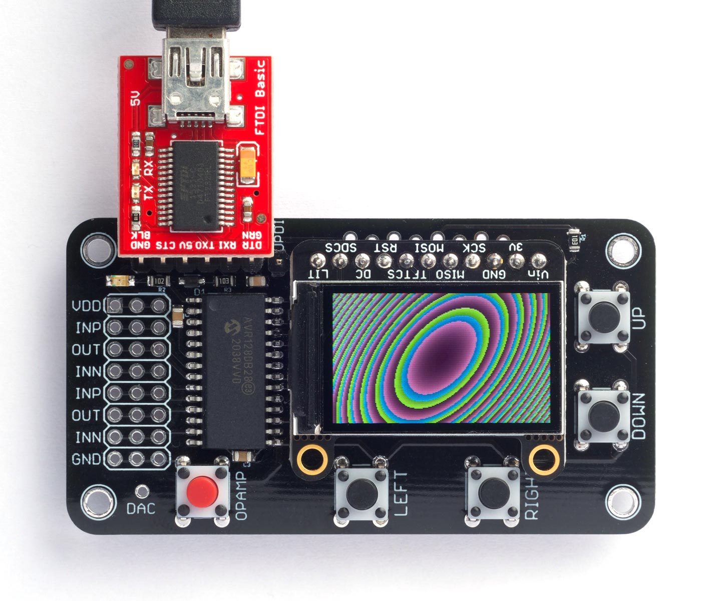
It also makes an interesting platform for running uLisp, with a colour graphics display that you can use with the uLisp graphics extensions:
It has five pushbuttons that you can read from Lisp, and an FTDI header that you can use to connect an FTDI USB to Serial interface, or FTDI cable, to allow you to interact with uLisp from the Arduino Serial Monitor, or a serial terminal.
For information about building the board, and a list of components, see: Pocket Op Amp Lab PCB on Technoblogy.
Get the version of uLisp for this board from Pocket Op Amp Lab on GitHub. This is based on AVR uLisp Version 3.5 with the addition of the graphics extensions.
Bear in mind that if you've chosen the AliExpress display option, the board should only be powered from 3.3 V, and the FTDI USB to Serial board or cable you use should be a 3.3 V version.
The board should work equally well with the AVR128DA28.
Specification
Size: 68.7 mm x 36.9 mm (2.7" x 1.45").
Display: 240 x 135 colour TFT.
Memory available: 2800 Lisp objects (11200 bytes).
EEPROM: 64 Lisp objects (256 bytes), allows you to save the Lisp workspace using save-image.
Processor: AVR128DB28
Clock speed: 24 MHz.
Installing a bootloader
The first step in installing uLisp on the Pocket Op Amp Lab board is to install a bootloader on the AVR128DB28 chip so you can subsequently upload programs from the Arduino IDE via the serial port, and use the serial monitor for debugging.
First install Spence Konde's DxCore from GitHub: see DxCore - Installation.
Then, in the Arduino IDE:
Choose the AVR DB-series (Optiboot) option under the DxCore heading on the Board menu.
Check that the subsequent options are set as follows (ignore any other options):
Board: "AVR DB-series (Optiboot)"
Chip: "AVR128DB28"
Clock Speed: "24 MHz internal"
Connect a UPDI programmer to the AVR128DB28. The DxCore now supports the following two options:
- Make a UPDI programmer from an Arduino Uno, or other ATmega328P-based board, as described in Make UPDI Programmer, and set the Programmer option to "jtag2updi".
- Use a USB to Serial board, such as the SparkFun FTDI Basic board [1], connect TX to the UPDI pin via a 4.7kΩ resistor, connect RX directly to the UPDI pin, and set the Programmer option to "Serial port and 4.7k (pyupdi style)".
Select the UPDI programmer from the Port menu. Then choose Burn Bootloader from the Tools menu to upload the bootloader to the AVR128DB28.
Installing and editing the Adafruit graphics libraries
The graphics extensions used in this version of uLisp require two Adafruit libraries. Install these from the Arduino IDE using Tools > Manage Libraries….
- Adafruit GFX Library
- Adafruit ST7735 and ST7789 Library
Because of some problems with Adafruit's GFX library you first need to make the following manual changes to the installed libraries in your Arduino > libraries folder:
- Remove the files Adafruit_GrayOLED.cpp and Adafruit_GrayOLED.h from the Adafruit_GFX_Library folder.
This is to stop the compile error "'BitOrder' has not been declared".
- Edit the file Adafruit_ST7789.cpp in the Adafruit_ST7735_and_ST7789_Library folder, as follows:
In the routine:
void Adafruit_ST7789::setRotation(uint8_t m) {
add a line:
_ystart--;
before the end of the routine.
This centres the display vertically correctly. You can check this after uploading uLisp by doing:
(draw-rect 0 0 240 135)
It should draw an unbroken white rectangle around the edge of the display.
Uploading uLisp
Now you've installed a bootloader you can upload uLisp via the serial port.
Get the version of uLisp for this board from Pocket Op Amp Lab on GitHub.
Then, in the Arduino IDE:
Choose the AVR DB-series (Optiboot) option under the DxCore heading on the Board menu.
As before, check that the subsequent options are set as follows (ignore any other options):
Board: "AVR DB-series (Optiboot)"
Chip: "AVR128DB28"
Clock Speed: "24 MHz internal"
This time the Programmer option is irrelevant.
Connect an FTDI board or FTDI cable to the FTDI header on the Pocket Op Amp Lab board.
This can be a USB to Serial board, such as the SparkFun FTDI Basic board [2]. Alternatively you can use an FTDI cable such as Adafruit's [3].
Connect other end of the FTDI cable to your computer's USB port, and select it from the Port menu.
Click Upload to upload uLisp to the AVR128DB28.
You should then be able to type or copy-and paste Lisp programs into the field at the top of the Serial Monitor window, and click the Send button or press Return to enter them.
Features
LED
The board has a yellow LED connected to pin 7 which you can flash with the following program:
(defun blink (&optional x)
  (pinmode 7 :output)
  (digitalwrite 7 x)
  (delay 1000)
  (blink (not x)))
Run it by typing:
(blink)
Exit from the program by entering ~.
You can save the blink program to EEPROM by typing the command:
(save-image)
You can now load it again after a reset by typing:
(load-image)
Note that there's not much EEPROM on the AVR128DB28, so you will be limited in the size of program you can save with save-image.
Buttons
The Pocket Op Amp Lab board has five buttons connected as follows:
| Button | Arduino pin |
| UP | 20 |
| DOWN | 21 |
| LEFT | 8 |
| RIGHT | 9 |
| OPAMP | 10 |
They should be defined as :input-pullup, and are pulled low when pressed.
I/O pins
The Pocket Op Amp board brings the op amp inputs and outputs to a prototyping area on the board. These pins correspond to Arduino pins 13 to 19, excluding 18 which is the DAC. They can all be used for digital I/O and for analogue input, and 13 to 17 can be used for PWM analogue output.
Analogue inputs
The AVR DA series chips support 12-bit analogue readings with analogread. By default they are 10-bit for compatibility with other Arduino boards, but you can select 12-bit with:
(analogreadresolution 12)
The analogue reference voltage can be selected with analogreference. For example:
(analogreference :internal2v048)
The options are :vdd or :default, :internal1v024, :internal2v048, :internal4v096, :internal2v5, or :external.
In addition to specifying a pin number to analogread you can also specify one of the following keywords:
- :adc-dac0 reads the value being output by DAC0.
- :adc-temperature reads the internal temperature sensor.
DAC
The AVR128DB28 has a DAC which the Pocket Op Amp board brings to a pin on the board labelled DAC. It is accessed using analogwrite to Arduino pin 18, and it generates an 8-bit output from uLisp. For example:
(analogwrite 18 128)
will set the DAC output to half of VDD, 2.5V.
Graphics extensions
The version of AVR uLisp for the Pocket Op Amp Board has the set of graphics extensions described in Graphics extensions. For example programs see Graphics utilities.
For example, the display at the start of this article was generated by this routine:
(defun rgb (r g b)
  (logior (ash (logand r #xf8) 8) (ash (logand g #xfc) 3) (ash b -3)))
(defun plot (w h)
  (let ((w2 (/ w 2)) (h2 (/ h 2)))
    (dotimes (xx w)
      (let ((x (- xx w2)))
        (dotimes (yy h)
          (let* ((y (- yy h2))
                 (f (/ (+ (* x (+ x y)) (* y y)) 8)))
            (draw-pixel xx yy (rgb (+ f w2) f (+ f h2)))))))))
Call it with:
(plot 240 135)
You can print a nicely formatted listing to the screen with:
(with-gfx (str) (fill-screen) (set-cursor 0 0) (pprint plot str))
- ^ SparkFun FTDI Basic Breakout - 5V on Sparkfun.
- ^ SparkFun FTDI Basic Breakout - 5V on Sparkfun.
- ^ FTDI Serial TTL-232 USB Cable on Adafruit.