Sipeed MAiX RISC-V boards
The RISC-V version of uLisp is designed to support microcontroller boards based on the RISC-V processor.
RISC-V is a free, open RISC Instruction Set Architecture that began development in 2010 at the University of California, Berkeley. A range of boards has been developed by Sipeed based on the K210, a RISC-V chip manufactured by Canaan Inc. of Beijing, China.
The first RISC-V boards supported by uLisp are the Sipeed MAiX boards, a range of boards in different form factors based on the Kendryte K210 RISC-V Dual Core 64 bit 400 MHz processor.
The RISC-V version of uLisp includes graphics extensions, to allow you to plot points, lines, shapes, and text to the MAiX colour TFT display. It also includes a RISC-V assembler that allows you to generate machine-code functions, integrated with Lisp, written in RISC-V code. The assembler itself is written in Lisp to make it easy to extend it or add new instructions.
Release 4.6a of uLisp allows you to use most of the 8 Mbytes of RAM for the Lisp workspace, giving a workspace of 500000 objects.
Boards
General features
Graphics extensions
To use the graphics extensions uncomment the compile option:
#define gfxsupport
The MAiX boards use a copy of the Adafruit GFX library provided in the Maixduino core, so if you have a copy in the Arduino libraries folder you should remove this before compiling uLisp.
For reference information about the graphics extensons see: Graphics extensions.
For some demo graphics programs see: Graphics utilities.
RISC-V assembler
For an overview of the RISC-V assembler and details of how to install it see: RISC-V assembler overview.
For a summary of the instructions in the RISC-V assembler see: RISC-V assembler instructions.
For example programs see: RISC-V assembler examples.
Setting up a Sipeed MAiX board
The MAiX boards are fitted with a USB-C socket. If your computer only has USB-A then you can use it with a USB-C cable [1] and USB-C Female to Type A USB 3.0 Male Adapter [2].
You can install the RISC-V version of uLisp on a Sipeed MAiX board using the Arduino IDE as follows:
- Download the RISC-V version of uLisp from the downloads page: Download and install uLisp.
- Add this URL to Additional Boards Manager URLs in the Arduino IDE Preferences:
http://dl.sipeed.com/MAIX/Maixduino/package_Maixduino_k210_index.json
- Open the Boards Manager… from the Board item on the Tools menu, search for Maixduino, and install Maixduino (K210) by Sipeed.
- Connect the Maixduino board to your computer using a USB cable.
- Select the appropriate board option from the Maixduino section on the Board menu.
- Set Port to /dev/cu.usbserial-xel_sipeed0 or similar.
- Set Programmer to k-flash.
You can leave the other options at their defaults.
Updating the serial buffer
As of uLisp Version 3.6 there is no longer a problem pasting large Lisp programs in via the Serial Monitor, so there is no need to change the serial buffer size from the default.
Installing uLisp
You should now be able to upload uLisp to the MAiX board.
Follow the instructions in Using uLisp to interact with uLisp on the MAiX board.
Sipeed Maixduino
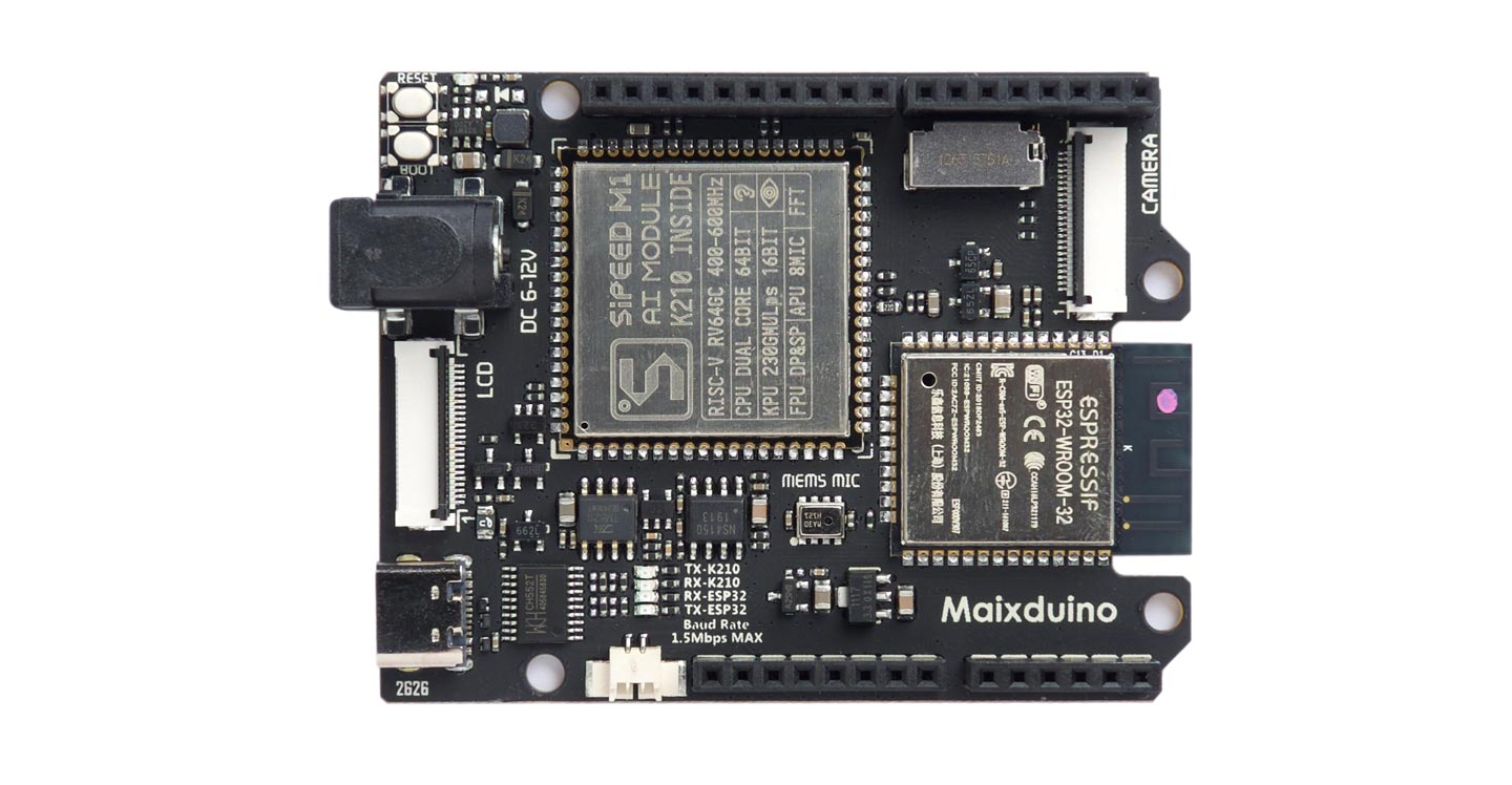
The Sipeed Maixduino is an Arduino Uno form factor board based on a Kendryte K210 RISC-V Dual Core 64 bit 400 MHz processor with Neural Network Processor (KPU) and Floating-Point Processor (FPU). It includes 8 Mbytes RAM, 16 Mbytes flash, a Micro SD card slot, and a LCD interface, making it an ideal platform for running uLisp.
Additional peripherals, some of which are not yet fully supported, include an ESP32 module to offer 2.4 GHz WiFi and Bluetooth 4.2, a MEMS microphone, a DVP camera, and an I2S audio output driving a 3W audio amplifier.
It's available with or without a compatible 320x240 Colour LCD display from Seeed [3] or Unmanned Tech in the UK [4].
Setting up the Sipeed Maixduino
To set up the Sipeed Maixduino see Setting up a Sipeed MAiX board.
Pin connections
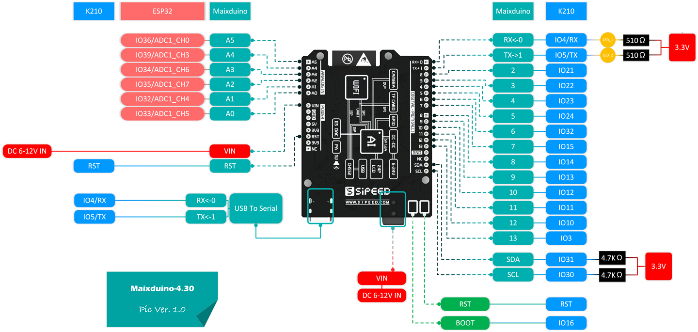
Digital inputs and outputs
The Maixduino provides 13 digital inputs or outputs accessible on the headers labelled 0 to 13. Each of these can be configured as an output, or an input with an optional pullup or pulldown. Note that unlike on Arduino boards, a pin won't operate as an input until pinmode has been called.
Analogue outputs
Any of the I/O pins can also be used as a PWM analogue output, using analogwrite with a value between 0 and 255.
Analogue inputs
The Maixduino Arduino core hasn't yet implemented the analogue inputs.
BOOT button
The BOOT pushbutton is connected to pin 16 with a 10kΩ pullup. You can read it with the following program:
(defun button ()
  (pinmode 16 nil)
  (loop
   (print (digitalread 16))
   (delay 500)))
Run it by typing:
(button)
TFT display
The Maixduino board provides a connector for a 320x240 Colour LCD TFT display:
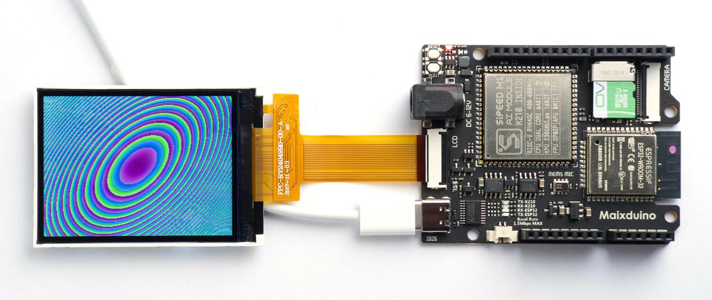
For reference information about the graphics extensons see: Graphics extensions.
For the demo program that created the above display and other demo graphics programs see: Graphics utilities.
Sipeed MAiX One Dock
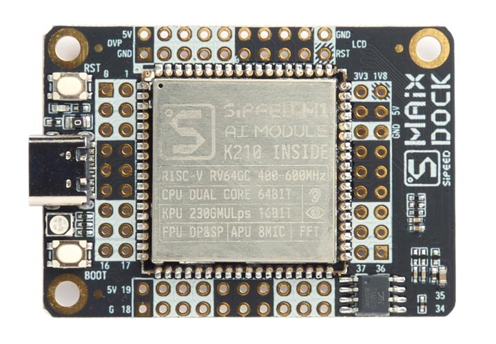
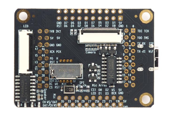
The Sipeed MAiX One Dock is a 52 x 37 mm board based on a Kendryte K210 RISC-V Dual Core 64 bit 400 MHz processor with Neural Network Processor (KPU) and Floating-Point Processor (FPU). It includes 8 Mbytes RAM, 16 Mbytes flash, a Micro SD card slot, a LCD interface, and a camera interface, making it an ideal platform for running uLisp. It also includes a MEMS microphone and a TM8211 I2S to analogue converter to give a stereo preamp output.
The board is available in two versions: the M1 shown above, or the M1w which adds Wi-Fi with an ESP8285 in the module and a uFL socket in the corner to allow you to connect the Wi-Fi antenna included in the package. The M1 is available with a compatible 320x240 Colour LCD display from Seeed [5]. The M1w is available with a compatible 320x240 Colour LCD display from Seeed [6] or Unmanned Tech in the UK [7].
Setting up the Sipeed MAiX One Dock
The Sipeed MAix One Dock is supplied with a dongle for converting between USB-C and USB-A; this dongle gave an overcurrent warning when I tried using it on my Mac, so if you have USB-A I recommend you steer clear of it and use a USB-C cable and a converter module instead as described above in Setting up a Sipeed MAiX board.
Unlike the other MAiX boards this board uses a CH340C USB-to-Serial converter, and it didn't connect to my Mac the first time I tried it. If you have problems getting it to connect you may need to install or update a driver for the CH340C [8].
To set up the Sipeed MAiX One Dock see Setting up a Sipeed MAiX board.
Digital inputs and outputs
The MAiX One Dock provides 48 digital inputs or outputs accessible on the headers labelled 0 to 47. Each of these can be configured as an output, or an input with an optional pullup or pulldown. Note that unlike on Arduino boards, a pin won't operate as an input until pinmode has been called.
Analogue outputs
Any of the I/O pins can also be used as a PWM analogue output, using analogwrite with a value between 0 and 255.
Analogue inputs
The MAiX One Dock doesn't provide any analogue inputs.
BOOT button
The BOOT pushbutton is connected to pin 16 with a 10kΩ pullup. You can read it with the following program:
(defun button ()
  (pinmode 16 nil)
  (loop
   (print (digitalread 16))
   (delay 500)))
Run it by typing:
(button)
RGB LED
The MAiX One dock board has an RGB LED connected to pins 14 (red), 13 (green), and 12 (blue). For example, you can make it blue by evaluating:
(pinmode 12 t)
(digitalwrite 12 0)
and then turn it off again by evaluating:
(digitalwrite 12 1)
The following program cycles the RGB LED through the 8 different combinations of colours:
(defun rgb ()
  (let ((leds '(12 13 14)))
    (mapc (lambda (p) (pinmode p t)) leds)
    (loop
     (dotimes (x 8)
       (mapc (lambda (p) (digitalwrite p (logand x 1)) (setq x (ash x -1))) leds)
       (delay 1000)))))
Run it by typing:
(rgb)
Exit from the program by entering ~.
All the I/O pins can also be used with analogwrite, so you can make the LED faint blue with:
(analogwrite 12 240)
For an analogue version of the above rgb program that you can run on the MAiX One Dock board see Mood light.
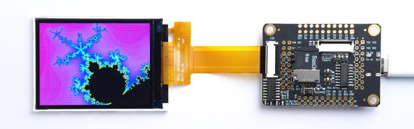
TFT display
The MAiX One Dock board provides a connector for a 320x240 Colour LCD TFT display which can use the uLisp graphics extensions; for example, here's the Mandelbrot demo program running on a MAiX One Dock:
For reference information about the graphics extensions see: Graphics extensions.
For the demo program that created the above display and other demo graphics programs see: Graphics utilities.
Sipeed MAiX BiT
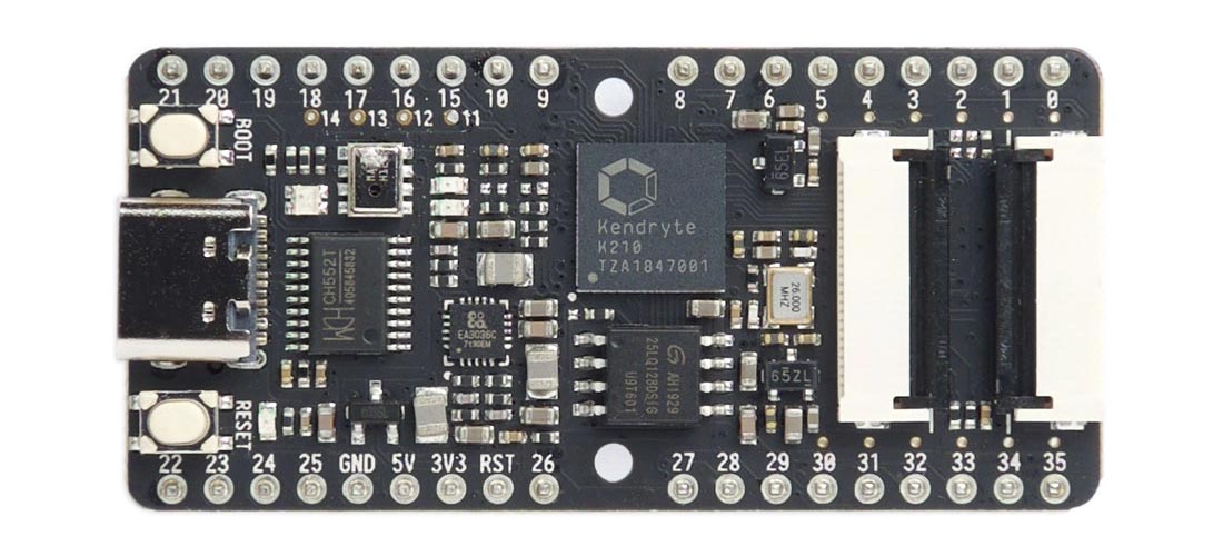
The Sipeed MAiX BiT board is the most compact of the MAiX boards, just slightly larger than the Adafruit Feather boards, and with two rows of headers making it suitable for use on a prototyping board. It is based on a Kendryte K210 RISC-V Dual Core 64 bit 400 MHz processor with Neural Network Processor (KPU) and Floating-Point Processor (FPU). It includes 8 Mbytes RAM, 16 Mbytes flash, a Micro SD card slot, a LCD interface, and a camera interface, making it an ideal platform for running uLisp. It also includes a MEMS microphone, but no I2S to analogue converter.
The board is available in two versions: the M1, or the M1w which adds Wi-Fi with an ESP8285 in the module and a uFL socket in the corner to allow you to connect the Wi-Fi antenna included in the package. The M1 is available with a compatible 320x240 Colour LCD display from Seeed [9]. The M1w is available with a compatible 320x240 Colour LCD display from Seeed [10] or Unmanned Tech in the UK [11].
Setting up the Sipeed MAiX BiT
To set up the Sipeed MAiX BiT see Setting up a Sipeed MAiX board. Note that you should choose the Sipeed Maix Bit-Mic Board option. The Sipeed Maix Bit option doesn't seem to work.
Digital inputs and outputs
The MAiX BiT provides 32 digital inputs or outputs accessible on the headers labelled 0 to 10 and 15 to 35. Each of these can be configured as an output, or an input with an optional pullup or pulldown. Note that unlike on Arduino boards, a pin won't operate as an input until pinmode has been called.
Analogue outputs
Any of the I/O pins can also be used as a PWM analogue output, using analogwrite with a value between 0 and 255.
Analogue inputs
The MAiX BiT doesn't provide any analogue inputs.
BOOT button
The BOOT pushbutton is connected to pin 16 with a 10kΩ pullup. You can read it with the following program:
(defun button ()
  (pinmode 16 nil)
  (loop
   (print (digitalread 16))
   (delay 500)))
Run it by typing:
(button)
RGB LED
The MAiX BiT board has an RGB LED connected to pins 14 (red), 13 (green), and 12 (blue). For example, you can make it blue by evaluating:
(pinmode 12 t)
(digitalwrite 12 0)
and then turn it off again by evaluating:
(digitalwrite 12 1)
The following program cycles the RGB LED through the 8 different combinations of colours:
(defun rgb ()
  (let ((leds '(12 13 14)))
    (mapc (lambda (p) (pinmode p t)) leds)
    (loop
     (dotimes (x 8)
       (mapc (lambda (p) (digitalwrite p (logand x 1)) (setq x (ash x -1))) leds)
       (delay 1000)))))
Run it by typing:
(rgb)
Exit from the program by entering ~.
All the I/O pins can also be used with analogwrite, so you can make the LED faint blue with:
(analogwrite 12 240)
For an analogue version of the above rgb program that you can run on the MAiX BiT board see Mood light.
TFT display
The MAiX BiT board provides a connector for a 320x240 Colour LCD TFT display which can use the uLisp graphics extensions.
For reference information about the graphics extensions see: Graphics extensions.
For demo graphics programs see: Graphics utilities.
- ^ Apple USB-C Charge Cable on Amazon.
- ^ USB-C Female to Type A USB 3.0 Male Adapter on Amazon.
- ^ Sipeed Maixduino for RISC-V AI + IoT on Seeed.
- ^ Sipeed Maixduino RISC-V Development Board on Unmanned Tech.
- ^ Sipeed M1 dock suit on Seeed.
- ^ Sipeed M1w dock suit on Seeed.
- ^ Sipeed M1w Dock AI Kit on Unmanned Tech.
- ^ How to Install CH340 Drivers on Sparkfun.com.
- ^ Sipeed M1 dock suit on Seeed.
- ^ Sipeed M1w dock suit on Seeed.
- ^ Sipeed M1w Dock AI Kit on Unmanned Tech.